
High Titanium White Masterbatch Factory: Key Practices for Superior Quality and Performance
2026-08-25
If your white masterbatch starts out bright but turns streaky or gray by the time it hits the film line, the problem probably isn’t the titanium dioxide—it’s the factory process behind it. High titanium loadings demand a level of control that many suppliers underestimate. Xinwancai treats that challenge as a core engineering problem, not an afterthought. The result is a masterbatch that delivers superior opacity, whiteness, and processability run after run. Here are the practices that set a high-performance white masterbatch factory apart.
Getting Titanium Dioxide Particles Fully Wetted and Dispersed
Achieving complete wetting of titanium dioxide particles is rarely a matter of simply dumping powder into liquid and stirring. The surface energy of TiO2, especially in pigment grades treated with inorganic oxides, resists penetration by water or organic solvents until mechanical and chemical aids are applied. High-shear mixing alone often leaves microscopic air pockets trapped around particle clusters, which later manifest as fisheyes, streaking, or uneven opacity in the final formulation.
A practical approach starts with pre-dispersing the powder in a small portion of the carrier under low speed, allowing the liquid to displace air from the particle surface gradually. Adding a wetting agent—typically a low-foaming surfactant or a polymeric dispersant with pigment-affinic groups—reduces interfacial tension and accelerates this process. The key is to introduce the powder slowly at the vortex edge of the mixer, not directly into the center, so that each particle is individually swept into the liquid rather than forming large agglomerates that resist further breakdown.
Once the initial wet-out is complete, dispersion requires sufficient mechanical energy to separate remaining aggregates without over-processing. Over-milling can fracture the crystal structure, raise viscosity, and even shift the undertone of the pigment. Monitoring torque or power draw during the dispersion phase helps identify the point where the viscosity stabilizes, signaling that the particles are fully wetted and uniformly distributed. At this stage, checking a drawdown or grind gauge will confirm that no undispersed specks remain, and the dispersion is ready for letdown.
Why Melt Filtration Matters More When TiO2 Loading Exceeds 70%
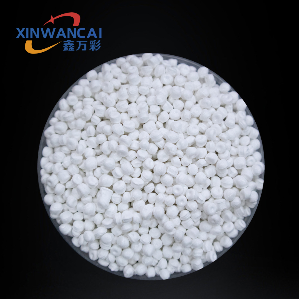
Once TiO2 concentration climbs past the 70% mark, the melt behaves less like a polymer and more like a dense slurry. Individual pigment particles and their agglomerates no longer stay evenly suspended, and any slight temperature fluctuation or shear gradient can trigger rapid particle clustering. This creates hard spots that not only ruin surface finish but also chew up downstream equipment. Filtration becomes the only reliable gatekeeper, catching these rogue clusters before they reach the die or spinneret.
At lower loadings, a standard screen pack can often handle the occasional oversized particle without much pressure buildup. But above 70%, the volume of near-micron debris rises sharply, and the filter medium itself starts to blind over. You need a different strategy: staged filtration with progressively finer meshes, or even depth media that can hold more contaminant without choking flow. A single coarse screen simply lets too many problem particles through, while a single ultra-fine screen will clog in minutes under that kind of pigment load.
What often gets overlooked is the impact of filtration on dispersion quality itself. As the melt passes through a well-designed filter pack, the shear forces help break apart soft agglomerates that survived mixing. This secondary dispersion step becomes critical when TiO2 is so densely packed that mixing screws can't reach every particle. Skipping or underestimating filtration at these loadings leads to streaking, raised surface defects, and ultimately a higher scrap rate that eats into the very cost savings that high filler content was supposed to deliver.
Keeping the Whiteness Stable From Pellet to Final Part
Hot runners, long barrel residence times, and aggressive shear all conspire against a clean white surface. Even a high-grade titanium dioxide can drift toward a faint yellow if the polymer matrix starts oxidizing before the part cools.
The real fix usually isn't more TiO₂. It's a layered stabilizer package that protects both the pigment and the base resin from the first heat cycle onward, so the pellet already carries the right defensive chemistry into the melt.
On the floor, keep an eye on regrind ratios and melt temperature. Small changes there show up as off-white patches or inconsistent gloss far quicker than most people expect.
Adjusting Screw Speed and Temperature for High-Filler Masterbatches
Working with high-filler masterbatches throws a wrench into standard extrusion settings. The sheer volume of calcium carbonate, talc, or barium sulfate raises melt viscosity dramatically, so blindly running your usual screw speed often leads to overheating or uneven dispersion. A practical starting point is to dial back screw RPM by 15–25% compared to a neat resin run. Watch the motor load and melt pressure closely: if the pressure spikes or the torque fluctuates wildly, you're likely pushing too fast and creating localized shear heat. Slower speeds give the filler particles time to wet out and distribute, but go too low and you risk poor homogenization or even barrel wear from abrasive fillers packing into the screw channels.
Temperature profiling needs a different mindset with high filler loadings. The feed zone should stay cool enough to prevent premature softening and bridging—typically 10–20°C below the polymer's melting point. The compression and metering zones, however, benefit from a slight bump (5–15°C above normal) to reduce melt viscosity just enough for the filler to slide into the polymer matrix without degrading the resin. Crucially, keep the overall barrel profile flatter than you would for unfilled material; sharp temperature gradients often cause filler agglomerates or surface roughness. The die head deserves special attention: set it 5–10°C lower than the metering zone to control die swell and prevent the strand from sagging or breaking.
The real skill lies in coordinating both variables on the fly. For a typical 70% calcium carbonate in polypropylene masterbatch, many operators settle around 80–120 RPM on a 40 mm single-screw extruder with barrel zones ranging from 160°C at the throat to 190°C near the die—but these numbers shift with filler type, particle size, and surface treatment. When dispersion quality drops or you see melt fracture, resist the urge to crank up the temperature first; try lowering screw speed by 10 RPM and observe for five minutes. Keep a log of torque, melt temperature at the die, and strand appearance. Over time, you'll develop a feel for the sweet spot where the filler distributes evenly without cooking the polymer or burning off coupling agents.
Detecting Agglomerates Before They Reach the Customer
Agglomerates that slip through unnoticed don't just create a quality complaint—they reset customer trust. The most practical line of defense is continuous inspection right at the point where powder or granules leave the blender, dryer, or mill. Inline vision systems and laser-based particle analyzers can flag oversized lumps in real time, long before the material reaches a holding bin or filling head. This shifts the focus from catching problems in retained samples to catching them while they are still correctable.
Choosing the right detection method comes down to the failure mode you are most likely to see. Soft, irregular clumps respond well to optical cameras paired with backlighting, while harder aggregates often show up more clearly with acoustic sensors or near-infrared scatter. Rather than chasing an absolute particle size spec, it helps to calibrate thresholds against what your customers actually notice on their line—screening tests, poor flow, or visible lumps in the final product. That practical baseline keeps false rejects low and the system from becoming an alarm no one listens to.
Once a detector flags an agglomerate, an automated diverter should remove that portion of the stream and log the event with a time stamp and batch reference. That record turns a one-off rejection into a traceable signal; if the same upstream mixer or a specific raw material lot keeps appearing, the root cause usually sits there. Reviewing moisture levels, mixing energy, and static buildup after repeated triggers closes the loop before the next batch ever gets near a customer.
Matching Carrier Resin to the End Application Without Overdosing
Carrier resin selection starts with matching the host polymer's melt behavior, not just its chemical family. A polyolefin carrier may work in polyethylene but fail in a polypropylene compound if the shear viscosity curves diverge too far. That mismatch shows up as poor pigment wetting, uneven distribution, or surface defects before you ever see a mechanical failure.
When the carrier and base resin share a similar viscosity under processing shear, dispersion happens faster and more uniformly. This means the masterbatch can be used at its designed letdown ratio without pushing the dosage higher to compensate for incompatibility. Overdosing is rarely about the additive being weak; it is usually the carrier failing to deliver the additive to the right phase.
A practical check is to narrow the melt flow index difference between carrier and host, especially when recycled or filled grades are involved. Run a minimum dosage trial first. If you keep increasing the percentage to fix streaking or brittleness, the carrier resin is not the right match, and no amount of extra masterbatch will correct that.
FAQ
High-load white masterbatch typically carries 70–80% titanium dioxide by weight, compared to 30–50% in standard grades. That extra pigment load boosts opacity and whiteness sharply, but it also makes dispersion far less forgiving. Without careful carrier resin selection and controlled shear during extrusion, you get agglomerates, die lines, or pressure spikes.
Dispersion quality decides whether the TiO2 particles act as individual light scatterers or as visible defects. Poorly wetted pigment clusters create surface roughness, reduce tensile strength, and can clog screen packs. In high-load grades, even a small fraction of undispersed pigment shows up as white specks in thin film.
The carrier is usually a low-melt-flow polyolefin wax or a polymer matching the end-use matrix. For blown film, an LLDPE-based carrier often works well; for injection molding, a PP-based carrier gives better compatibility. Some producers blend EVA or polar waxes to improve wetting of the TiO2 surface.
Thermal yellowing often comes from excessive barrel temperatures, long residence time, or the photocatalytic activity of uncoated TiO2. Keep melt temperatures in the range recommended for the carrier, add a small amount of antioxidant and UV stabilizer, and use fast strand cooling before pelletizing. Regular screw and barrel cleaning also prevents charred material from contaminating later batches.
Batch release should include a filter pressure test to catch dispersion issues, colorimeter readings for L* and yellowness index, melt flow rate, and ash content to confirm actual titanium dioxide loading. A small blown film or injection molding trial is also valuable because it reveals surface quality and opacity that lab data alone can miss.
Food-contact use depends on the regulatory status of every ingredient, not just the TiO2. The factory should maintain migration test reports, raw material compliance statements, and good manufacturing practice records. In some regions, specific purity requirements or particle size restrictions apply, so the customer must confirm the final article meets local food-contact rules.
Consistency starts with gravimetric feeding of all components and fixed screw speed and temperature profiles. Inline melt filtration with pressure monitoring catches early signs of agglomeration. Keeping retention samples from each lot and rechecking them after storage helps trace any later complaint back to the exact production run.
Conclusion
Achieving a reliably bright white masterbatch with titanium dioxide loadings above 70% starts with complete wetting and dispersion of the pigment. The high shear forces inside the extruder must be paired with a carrier resin that actually wets the TiO2 surface, otherwise dry agglomerates survive and later show up as specks in film or molded parts. Once dispersion is under control, melt filtration becomes non-negotiable. At that filler level, even small hard particles or undispersed pigment clusters will tear screens or pass through as defects, so the filter setup has to be sized for the actual viscosity and throughput rather than copied from a lower-filler line. Screw speed and barrel temperatures then need to be tuned together—too fast creates shear heating that can yellow the resin, while too slow starves the melting zone and leaves pigment poorly distributed.
Keeping whiteness stable from pellet to final part means monitoring not just the TiO2 grade but also the interaction between carrier resin, processing temperature, and any additives that can shift color over time. Regular agglomerate checks on the pellet stream, whether by pressure rise tests or quick film castings, catch problems before they reach a customer's hopper. Finally, the carrier resin must match the end application without being overdosed; an overly high melt flow carrier can dilute mechanical properties, while an overly viscous one makes dispersion harder. The best factories treat these practices as a single loop—dispersion quality, filtration, thermal profile, whiteness retention, agglomerate detection, and resin selection all feed back into each other, and small adjustments in one area often prevent larger defects downstream.
Contact Us
Contact Person: JACK
Email: [email protected]
Tel/WhatsApp: 86 18650130917
Website: https://www.xinwancai.com/