
Inside a Bogie Hearth Furnace Factory: How Precision Heating Systems Are Built
2026-09-16
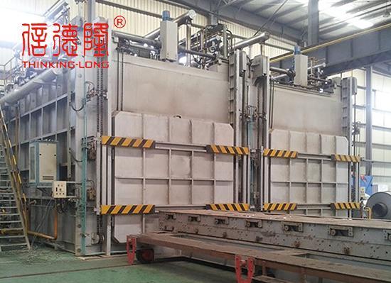
A bogie hearth furnace is a precision heating system that doesn't hide how it was made—every weld, brick, and wire tells you whether it will hold temperature. At THINKING-LONG, we treat that build process as the product itself. Step onto the factory floor and see how steel, insulation, and automation come together before the first heat cycle.
Cutting and Welding the Load-Bearing Frame
Experienced site crews usually mark every loaded column, beam, and brace before any torch or saw comes near the frame. Temporary props or screw jacks are placed on both sides of the intended cut line, and a small load is applied while deflection is monitored. Skipping this step is how a seemingly minor cut in a secondary member turns into a sudden shift in the whole structure, because the load path rarely follows the obvious visual line.
The cutting method is chosen by steel thickness and access, not by what is fastest. Thick flange plates are often cut with a track-mounted bandsaw or a circular saw to keep the heat-affected zone small. Flame cutting is reserved for areas where mechanical tools cannot reach, and the cut face is then ground back to remove oxidized and hardened material before any welding starts. Squareness and bevel angles are checked with a gauge, not just by eye.
Welding on a load-bearing frame demands filler metal that matches or exceeds the base material, with low-hydrogen electrodes or flux-cored wire as the usual choice. The weld sequence runs from the center of the joint outward in a balanced pattern to pull residual stress down. After the weld cools for at least a full day, nondestructive testing focuses on undercut, lack of fusion, and delayed cracking at the node. Any defect beyond the acceptance limit is ground out completely and rewelded, rather than buried under a cosmetic pass.
Machining Hearth Surfaces to Micron Flatness
Achieving micron-level flatness on hearth surfaces demands a departure from conventional fly-cutting routines. The process begins with careful stress relieving of the base plate, followed by rough facing that leaves a deliberate 0.05 mm witness ring. This ring acts as a visual reference for the finish pass, where a single-point diamond tool traverses the entire diameter without step-over marks. Temperature drift is countered by monitoring the machine's thermal growth in real time, adjusting the tool offset every few minutes. The result is a surface where reflected light moves in a single unbroken band, confirming deviations under three microns.
Tool geometry plays a quiet but decisive role. A zero-rake polycrystalline diamond insert with a 2 mm nose radius keeps cutting forces radial, preventing edge collapse on thin hearths. Spindle runout is mapped prior to the final pass, and any asynchronous error above 0.5 microns triggers a spindle warm-up cycle. Coolant is avoided entirely; instead, a low-volume air jet clears chips without inducing thermal shock. Operators learn to read the faint chatter marks left by the previous pass, adjusting feed per revolution until those marks vanish, meaning the tool is cutting only the peaks left behind.
Flatness verification on such surfaces requires more than a simple indicator sweep. A phase-shifting interferometer is placed directly over the hearth, producing a full-field height map in under a minute. Areas that show low-order bowing are corrected not by further machining but by gentle lapping against a calibrated granite flat, using a loose abrasive slurry that removes only a few hundred nanometers per minute. The final acceptance test involves drawing a straightedge across the diameter and checking for light gaps with a monochromatic source; any interference fringe count above two fails the part. Once passed, the hearth is cleaned with anhydrous isopropanol and sealed against oxide growth before installation.
Installing Heating Elements That Spread Heat Evenly
Getting even heat starts before you ever turn the power on. Check the physical layout of the heating element against the surface it is meant to warm. For flat panels or floors, keep spacing between runs consistent—crowding one section while leaving another sparse creates hot and cold bands that are almost impossible to fix later. Use a straightedge and chalk line to mark parallel paths, and double-check that the element sits fully in contact with the substrate. Any place where the wire lifts away or loops over itself will trap heat and shorten the life of the element.
The hardware you choose can quietly undermine an otherwise careful layout. Use the clips, channels, or adhesive recommended for the specific element type rather than improvising with wire staples or tape that can pinch or shift under thermal cycling. When embedding in concrete or under tile, leave the slight slack the manufacturer specifies; too tight and the element will pull against its anchors as it expands, too loose and it can float toward the surface. After the element is in place but before covering it, run a low-voltage test and scan the area with an infrared thermometer to spot any dead zones or uneven resistance.
Thermal mass above and below the element also shapes how evenly heat reaches the room. A reflective barrier or insulation board underneath pushes more heat upward, but it has to be cut cleanly around the element without creating air pockets. Above the element, avoid thick overlays in some areas and thin in others, because that changes how quickly heat moves through the covering. If you are installing multiple elements for one large space, wire them in zones that match the room’s actual use rather than one oversized loop, so you can fine-tune output later without tearing up the floor.
Layering Refractory Insulation for Thermal Lockdown
Effective thermal lockdown rarely comes from a single refractory product; it emerges from how layers with different densities and thermal conductivities are arranged. Dense hot-face materials handle direct flame impingement and mechanical wear, while lightweight backup layers slow conductive losses and keep the shell temperature within limits. The transition between these layers matters more than the thickness of any one board or blanket.
A practical stack might pair a high-alumina brick or castable at the hot face with microporous panels and a calcium silicate board behind it. The microporous layer does the heavy lifting at intermediate temperatures, where its conductivity is remarkably low, but it needs protection from both high heat and moisture. Adding a thin reflective foil between layers can further interrupt radiant transfer, though it only works when the gap stays intact during thermal cycling.
Installation details decide whether the system actually locks heat in. Joints should be staggered, edges compressed just enough to close gaps without crushing low-density insulation, and anchors isolated to avoid creating metal heat paths. Even small openings around thermocouple ports or door seals can undermine the entire stack, so every penetration needs its own layered collar or plug.
Mounting the Bogie Drive and Guide System
Mounting the bogie drive and guide system starts with aligning the gearbox output shaft to the axle pinion. A slight angular offset here will show up later as uneven wear on the coupling and can lead to premature bearing noise. Use a dial indicator against the coupling flange while rotating the axle by hand, and shim the motor bracket until runout stays under 0.10 mm.
Once the drive unit is seated, the guide system—usually a combination of journal boxes, lateral stops, and yaw dampers—has to be fitted in a specific order. The lateral stops are set with the bogie frame on level track, not lifted, so that the free gap between stop and axlebox matches the bogie's design clearance. Tightening the yaw damper bolts before this check often locks in a preload that makes the wheelset hunt at higher speeds.
After the initial torque pass, recheck all mounting bolts within the first few service hours. The bedding-in of the rubber-metal bushes and the painted contact surfaces relaxes bolt tension, especially on the reaction rod and the torque arm. A quick pass with a torque wrench and a visual check for cracked paint around the bolt heads will catch loose joints before they cause a misaligned drive.
Verifying Uniformity with Loaded Temperature Mapping
A loaded temperature mapping study starts with the assumption that empty-chamber performance rarely reflects real storage conditions. Racking, product containers, and even packaging materials alter airflow paths and create localized heat pockets. To get a meaningful uniformity picture, sensors should be arranged in a three-dimensional grid that includes the geometric center, each corner, and spots adjacent to doors, walls, and any known air return vents. Running the mapping for a duration that covers normal door openings or defrost cycles adds context that static spot checks cannot provide.
Uniformity under load is often judged by two straightforward metrics: the spread between the highest and lowest logged temperatures, and the deviation from the set point at each sensor location. A chamber can hold an average temperature comfortably within range while a single poorly ventilated shelf drifts out of specification. For that reason, placing sensors inside representative product loads—or using thermal mass simulators—offers a sharper view than attaching probes to open shelving. Acceptance limits should be set before data collection begins, not negotiated after the fact.
Interpreting the results requires attention to timing as much as location. Short-lived excursions during defrost cycles or brief door openings may be acceptable if the product's thermal mass stays within its labeled range. However, sustained stratification between upper and lower zones often points to airflow design problems rather than sensor placement error. A repeat mapping after adjusting shelf spacing, fan speed, or load configuration confirms whether the fix actually improved uniformity. Without that verification step, the mapping remains a documentation exercise rather than a control measure.
FAQ
The floor starts with heavy I-beams being cut and welded into the bogie frame. Workers check alignment with laser levels before any brick goes in, because a slight twist in the frame will cause the door seal to fail later. Raw material storage nearby holds ceramic fiber modules, firebrick, and nickel-chromium heating coils, all tagged with batch numbers.
We mount the coils in sinuous patterns along the side walls and sometimes under the hearth. The spacing is not uniform; it gets tighter near the door and corners where heat loss is higher. After installation, we run a thermal mapping test with dummy loads and adjust element positions if any zone is off by more than a few degrees.
The entire hearth rolls out on rails, so a crane can load large structures directly onto the platform instead of sliding them through a narrow opening. This reduces risk of damage and allows a furnace to handle pieces like wind turbine shafts or pressure vessels that might weigh several tons and need support across their full length.
The walls combine lightweight ceramic fiber with denser firebrick in areas that face mechanical wear. Multiple layers with staggered joints block heat leakage. A well-insulated furnace can hold a setpoint within plus or minus five degrees Celsius, which matters for heat treatment processes like annealing where even a small drift ruins material properties.
They close the door against the hearth and use a thin feeler gauge around the perimeter. Then they run a positive pressure smoke test, pumping air into the chamber and watching for wisps escaping. If any gap is found, the door clamps are adjusted or the seal gasket is replaced until the smoke stays inside.
Most units get a PLC with recipe storage, so operators can program ramp rates, soak times, and cooling cycles. We also install independent thermocouples that act as a safety interlock: if the main controller fails or the temperature overshoots, the safety circuit cuts power to the heating elements automatically.
Aerospace and automotive suppliers often ask for controlled atmosphere options, like nitrogen purging, to prevent oxidation. Forging plants sometimes need a bogie that can withstand repeated quenching loads, so we reinforce the platform with castable refractory and add extra cross-bracing. Each modification changes the heating profile, so we re-run simulations before final assembly.
The furnace is heated to its maximum rated temperature and held there for several hours while technicians record energy consumption, uniformity, and surface temperatures of the outer shell. A data logger tracks all thermocouples, and the customer is invited to witness the test. Only after the data meets the agreed specification does the furnace get crated for delivery.
Conclusion
On a bogie hearth furnace factory floor, heavy steel sections are cut and welded into the load-bearing frame. Every joint is checked for alignment because the entire furnace will rest on that skeleton. Once the frame passes inspection, the hearth surface is machined to micron-level flatness. This is not about looks; any high or low spot will cause uneven heat transfer when the load rolls in. The bogie itself has to move smoothly, so the flatness of the hearth and the precision of the drive and guide system determine whether a multi-ton load can be positioned without binding or drifting. Heating elements are then installed across the roof and sidewalls. Their arrangement is deliberately varied to make up for heat loss at the door and corners, keeping the temperature steady from edge to edge.
After the elements are secured, refractory insulation goes up in layers. Dense firebrick, ceramic fiber board, and lightweight backup insulation are combined to lock heat in while keeping the outer shell cool enough to touch. The last stage is loaded temperature mapping. A test load fitted with thermocouples goes through a full heating cycle, and the data shows exactly how uniform the heat is under real production conditions. If a cold spot shows up, burner or element zones are adjusted and the test is repeated until the temperature spread falls within the specified tolerance. That kind of verification separates a furnace that merely heats from one that heats predictably. In the end, the factory is not just assembling steel and brick; it is building a controlled thermal environment where every millimeter and every kilowatt has a job to do.
Contact Us
Contact Person: Qian Xijun
Email: [email protected]
Tel/WhatsApp: 8613961736750
Website: https://www.thinkinglong.com/