
ODM Plastic Push Pull Connectors: What to Know Before Choosing
2026-11-18
Industrial designs keep shrinking, yet the connection points often carry the most risk. If you are evaluating ODM plastic push pull connectors for medical, outdoor, or high-cycle applications, the usual spec sheet will not tell you enough about mating feel, cable strain relief, and long-term locking security. REUNION has seen too many projects delayed by connectors that look right on paper but fail in the field. Before you lock in a supplier, there are a few overlooked factors that deserve your attention.
Plastic Grades That Outlast the Sales Pitch
A data sheet can make almost any resin look capable on paper. The real test usually comes after weeks of thermal cycling, chemical exposure, or constant load. Some grades hold their dimensions and surface finish long after the initial numbers stop being quoted. Others quietly develop microcracks or lose clamp load, and that is when the sales pitch ends and the actual cost begins.
The difference often sits in the compounding, not just the base polymer. A glass-filled polypropylene may carry an impressive flexural modulus, but if the stabilizer package is thin, it will turn brittle under heat before the equipment reaches its first major service interval. In contrast, well-formulated engineering grades such as certain nylons and acetals stay predictable because they are built around long-term creep and chemical resistance, not just a single tensile figure.
When comparing options, it helps to ask for aging data, retention of properties after exposure, and examples from similar operating conditions. A grade name or a glossy comparison chart rarely tells you how the material will behave three years into a messy production environment. The plastics that outlast the pitch are usually the ones with a documented track record rather than the boldest headline numbers.
Push Pull Locks Worth Mating by Hand
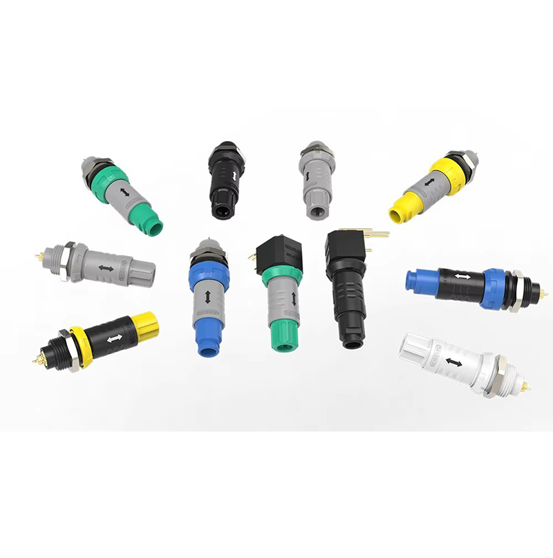
A push-pull lock only earns its place when the mating action feels deliberate without demanding force. The real test is not whether the collar snaps forward, but whether your thumb can guide the plug home while the shell stays square to the socket. If the keyway alignment is even slightly vague, you end up rocking the connector, and that sideways pressure shortens contact life faster than repeated cycling.
Hand mating also exposes the difference between a well-cut latch and a stiff mechanism disguised by a spring. A good lock should let you feel the ramp climb, then the detent release, then the collar settle into the locked position. That sequence gives you a mechanical confirmation no indicator light can replace. When the action is too soft, it feels ambiguous; when it is too sharp, technicians start avoiding full engagement just to save their fingertips.
Field conditions rarely match the bench. Dirt, cold gloves, and awkward panel angles punish locks that need perfect alignment or a hard shove. Designs worth mating by hand keep the grip surface large enough for a gloved thumb, taper the entry so the connector self-corrects, and keep the pull force low enough to avoid snapping the cable backward. Those details only show up after you ignore the specification sheet and pick up the parts yourself.
Keying and Color Choices Before Tooling Begins
Most keying problems are locked in long before a single node or mask is created. When footage lands with uneven green spill or compression artifacts, the real decision is not which keyer to use but whether the shot should be keyed through luminance, chroma, or a hand-built combination of both. Looking at the plate in linear space, checking edge motion on a frame-by-frame basis, and marking where hair, glass, or motion blur crosses the background reveal the places a default key will tear. Those observations shape a rough garbage matte plan before any tool touches the timeline.
Color choices work the same way. Pulling a key under a warm display or in an uncalibrated viewer often pushes the background toward cyan or magenta without being noticed until the shot is viewed elsewhere. A more reliable habit is to set a neutral reference frame early, run a temporary desaturated copy to judge contrast, and decide whether the background will sit close to the original plate or be pushed toward a deliberate grade. That choice affects how aggressive the edge treatment needs to be, because a heavily stylized background hides more fringe than a clean, near-plate match.
Treating the two decisions as separate stages usually creates rework. If the key is refined on a green screen clip and then dropped into a scene with warm practical lighting, the edges will need to be rebalanced anyway. Spending a few minutes before tooling begins to place a rough color swatch, check skin tone separation, and compare the foreground against the intended background helps lock a direction. The actual keying then becomes a matter of protecting that decision instead of discovering it halfway through the comp.
Panel Cutout Tolerances That Cause Real Friction
Panel cutouts rarely cause trouble on the drawing board. The real friction starts when a fabricated enclosure arrives with a cutout that is only a millimeter over, and suddenly a connector floats sideways, a gasket loses its sealing line, or a row of mounting holes no longer lines up without forcing screws. Tolerances that look safe in isolation often stack up across the panel, the component, and the cutting method—laser, punch, or router—until the assembly team is left filing edges and shimming brackets just to make parts fit the way the CAD model promised.
The most persistent problems come from rectangular and irregular openings. If a display bezel is specified with a tight clearance, any slight bow in the panel or burr along the cut edge turns a drop-in operation into a press-fit struggle. On the opposite end, an oversized cutout may seem forgiving, but it exposes the gap around the component, weakens the corner radii, and shifts the visual alignment that industrial designers count on. Even worse, when a gasketed component sits inside the opening, the cutout tolerance directly controls compression. Too small and the gasket tears or bulges; too large and dust, moisture, and light leak through the same gap that was meant to seal.
A better approach is to treat cutout tolerance not as a single number but as a working range tied to the component's real behavior. Suppliers often publish recommended hole sizes with plus and minus values that assume flat, rigid panels—conditions that rarely survive sheet metal bending, powder coating, and shipping. Designers who add a practical allowance for edge finish, panel deflection, and alignment pins can avoid the last-minute grinding, offset brackets, and awkward conversations that happen when a panel that met print still does not fit in the field.
Seal Integrity After Repeated Mating Cycles
A connector's seal is rarely tested in a single engagement. It gets pushed, pulled, and rotated through dozens or hundreds of mate-demate sequences, and the resilient member must hold its shape throughout. The real question is whether the material can recover its original geometry after each cycle without developing micro-tears, permanent compression set, or surface abrasion that quietly opens a leak path.
Repeated mating often reveals weaknesses that a one-time pressure test entirely misses. The wiping action of the pin entering the socket can shave microscopic fragments from the seal lip, especially if alignment is slightly off. Over time, those fragments accumulate, reducing contact pressure unevenly. Temperature swings between cycles compound the problem, as the elastomer expands and contracts against a rigid housing, gradually loosening the interference fit that initially made the seal trustworthy.
What separates a robust design from a marginal one is how the sealing interface is protected during blind mating. A lead-in chamfer that guides the pin without scraping the seal, a groove geometry that allows the material to flex without pinching, and a durometer selected for resilience rather than just hardness all matter more than the material's rated temperature range. Field data tends to confirm this: connectors that survive 500 cycles with zero leakage typically show no visible wear on the seal's working surface, whereas failures at 100 cycles almost always trace back to a sharp edge or an undersized relief cut.
What Factory Test Reports Actually Reveal
Factory test reports are rarely as straightforward as the final stamp suggests. Behind the pass/fail result sits a record of drift, scatter, and borderline readings that can reveal whether a production line is stable or merely surviving inspection. A batch can clear every threshold while the data still shows a slow climb in internal pressure or a narrowing margin on key dimensions—early signs that something is wearing, loosening, or drifting out of alignment.
Reading these reports well means ignoring the verdict long enough to notice the shape of the measurements. Repeated values clustered near an upper limit, uneven wear across mold cavities, or rising electrical resistance from one shift to the next tend to show up long before defects become visible in the field. In that sense, a factory test report is less a certificate of quality and more a trailing indicator of process health, one that rewards attention to small changes rather than a glance at the final column.
FAQ
It usually means the supplier already has a working connector platform and modifies the housing, strain relief, pin insert, or keying to fit your device. You avoid starting from a blank sheet, but you still get a part that looks and behaves like a custom design.
They can be, but the material matters more than the word plastic. Glass-reinforced PBT, PSU, and PEEK behave very differently. For frequent mating, rough handling, or exposure to cleaning agents, ask for reinforced engineering resins rather than standard ABS or nylon.
Look closely at insulation resistance, creepage and clearance, and whether the materials can handle the required sterilization method. Autoclave cycles will rule out many plastics quickly. Also confirm the contact plating because low-quality gold flash can degrade after a few dozen cycles.
Some use a spring-loaded sleeve with internal balls, others rely on a simple latch ring or a plastic snap. The difference shows up in how much force it takes to mate, how secure the lock feels, and how easily it can be cleaned. A soft or vague lock is often the first thing users complain about.
Most can change the cable exit angle, add colored rings or overmolded strain relief, adjust the pin count, or create a mixed power and signal layout. Some will also customize the locking sleeve color and print your logo directly on the body.
Ask for the actual IP rating under pressure or spray, not just a static rating. Also check whether the cap or panel socket stays sealed when unmated. Many connectors pass IP67 when mated but leave the panel opening vulnerable during cleaning.
Use mechanical keying plus visible color coding instead of relying on labels alone. Request different key positions for each port and choose body colors that remain distinguishable under low light or after repeated cleaning.
Tooling amortization, custom cable assembly labor, and testing eat into the budget quickly. If the supplier has to build a new mold for a housing variant or validate a new contact arrangement, that upfront cost may overshadow the per-piece connector price.
Conclusion
Before committing to an ODM plastic push-pull connector, the plastic grade deserves more attention than the glossy brochure. A PA66 or PBT body can feel sturdy on day one and still crack around the latch after a few hundred cycles if it was chosen for cost rather than impact resistance and chemical exposure. Equally telling is the lock itself: the best push-pull designs give a clean, deliberate snap when mated by hand, without requiring a hard yank or a precise wrist angle. If keying and color options are settled before tooling, field mistakes drop sharply because technicians can read the connector face at a glance instead of guessing from a nearly identical shell.
Panel cutout tolerance is where many projects stall. A connector that fits a perfect CAD hole may still bind or wobble once the enclosure arrives with real manufacturing variation. Ask for the allowed cutout range, not just a nominal diameter, and test the fit across that full band. Seal integrity also changes over time; a connector rated IP67 may hold on the first mating, yet the o-ring or gasket can deform after repeated insertion, especially with side loads or rough handling. Factory test reports usually reveal more than a datasheet: look for mating cycle data, leakage results after cycling, and whether the tested samples actually match the plastic and seal material being quoted for your build.
Contact Us
Contact Person: Hayley Liang
Email: [email protected]
Tel/WhatsApp: +86 13480625451
Website: https://www.reunion-china.com/