
Performance Cylinder Head Factory Insights for Building Powerful Engines
2026-08-19
What separates a mild street engine from a track-ready beast? It’s rarely the cam or the turbo—it’s the cylinder head. Yet most builders overlook the factory-level insights that make a head truly perform. At DDR, we obsess over port velocity, combustion chamber shape, and thermal efficiency. Here’s what we’ve learned from building heads that push engines to their limits.
The Porting Benchmarks We Use Before a Single Casting Is Poured
In our shop, the first pour doesn't happen until a port design clears a set of numbers we've pulled from years of tear-downs and dyno sessions. We're not chasing a single peak CFM figure. Instead, we look at discharge coefficient across the valve lift curve, velocity distribution at the apex of the short-turn, and how the port behaves at low lift where the valve spends most of its time. If a core box or 3D-printed test piece can't match those marks, there's no point mixing metal.
The bench itself is only as useful as the baseline it's referenced against. We keep a library of known-good and known-bad ports, cast from previous generations, and every new shape gets compared on the same depression, same bore adapter, same valve job. A port that flows 320 CFM but goes turbulent at .450 lift gets flagged before a pattern is cut. That's the kind of problem you don't want to discover after you've already poured a dozen blocks.
Wet flow is another gate. We watch where fuel droplets pool or shear, because a dry flow number can lie to you. If the mixture separates at the apex or stacks up on the far wall of the bowl, the port gets revised. Only after the dry and wet data align with the target window do we commit to a casting run.
Why Valve Seat Runout Costs More Horsepower Than a Bad Cam
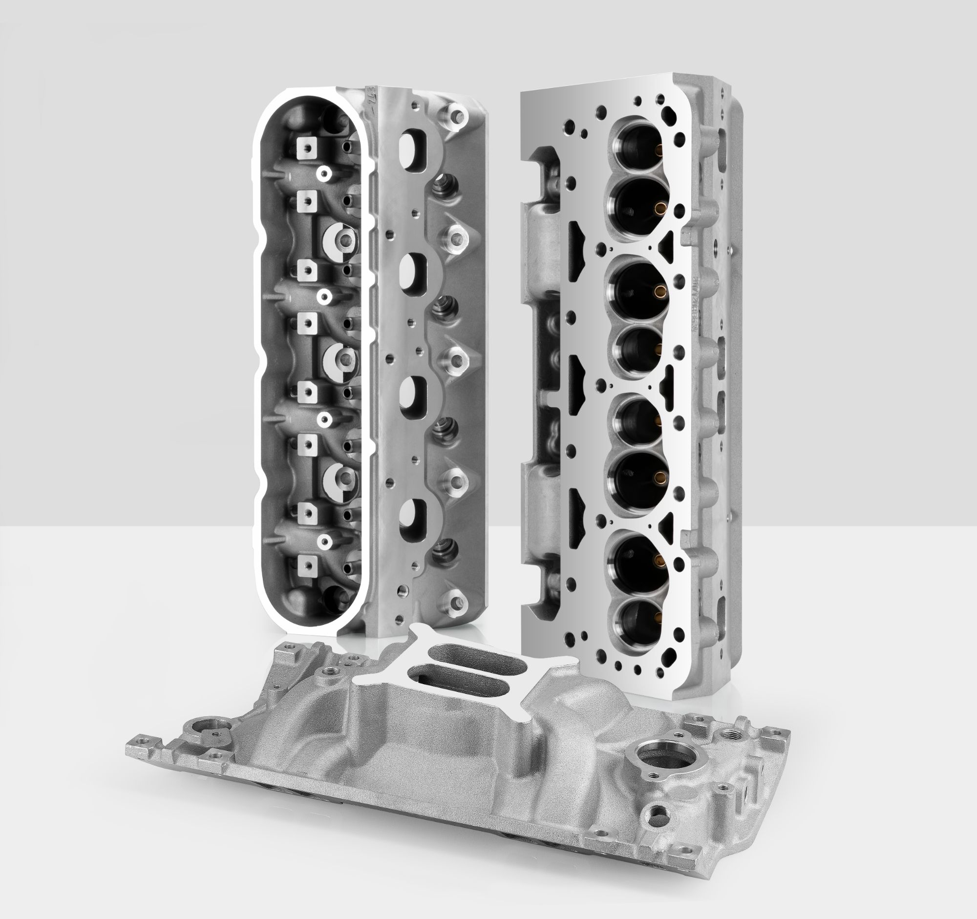
Most builders will spend hours degreeing a cam, yet they never check if the valve actually sits flush. That’s a costly mistake. Valve seat runout—where the seat isn’t concentric with the guide—means the valve head lands slightly cocked every time it closes. At low lift, which is where a street engine spends most of its life, the curtain area around the valve is already tiny. Runout chokes that area further and lets combustion pressure sneak past the seal. A few thousandths of runout can knock 10–12 cfm off a flow bench at .200" lift, and the dyno sees it as a loss across the entire curve—not just at peak.
A worn or wrong cam usually kills top-end power, but the engine still pulls cleanly down low. Seat runout is different. It causes the cylinder to leak on the compression stroke and dilutes the next intake charge with leftover exhaust. That hurts torque everywhere, softens throttle response, and can make the idle hunt. On a typical small-block, you might lose 15–20 hp from moderate runout while a bad cam grind only costs 8–10 hp at the top. Before swapping cams, pull the valves and spin them with a dial indicator. The fix is cheaper, and the power comes back instantly.
Our CNC Program Isn't About Bling—It's About Repeatable Flow
Most shops chase shiny toolpaths and flashy finishes, but we've learned the hard way that a CNC program's real value shows up when you run it fifty times on a Tuesday afternoon. Repeatable flow means the same feeds, the same order of operations, and the same predictable results every single cycle—no surprises when you're already behind schedule.
That's why our programs are built around stable workholding datums, conservative cutter engagement, and post-processors tuned to the actual machine on the floor. We don't optimize for the demo video; we optimize for the operator who's running three machines and doesn't have time to babysit a finicky toolpath.
When a program flows repeatably, setup time shrinks, scrap rates flatten, and you stop dreading the second run. It's not glamorous, but it's the difference between a part that looks good once and a process that earns money every day.
Casting Shift, Core Shift, and the Hidden Geometry Killers
Most foundry engineers learn early that a casting's nominal blueprint means little if the tooling wanders. Casting shift happens when the cope and drag halves of the mold slip out of alignment, often by a millimeter or two. That small slide can leave a visible parting line step, but the real damage hides inside—walls that taper the wrong way, bosses that no longer line up with machined faces, and sudden stress risers that only show up after the part cracks in service.
Core shift is a quieter cousin. The core sits in the mold cavity, held by prints or chaplets, but metal pressure and buoyancy can nudge it before solidification locks everything in place. A shifted core might move a water jacket off center, thin out an oil gallery wall, or create an internal passage that drifts too close to a mounting flange. These are not obvious defects on the surface—no rough patches or blowholes—just a geometry that no longer matches the intent, waiting to fail a pressure test or fatigue test.
The hidden geometry killers are the cumulative effects: a half-degree of core tilt plus a slight cope drag, combined with pattern wear that adds a fraction more stock on one side. Individually, each shift stays within tolerance. Together, they stack into a wall section that is forty percent thinner than designed, or a sealing face that is no longer parallel to its mate. Tracking these requires more than final inspection—it means mapping the actual molded geometry against the CAD model at multiple cross sections, then correlating those maps back to molding variables, core setting forces, and tooling wear patterns before the first pour.
Chamber Softening and Quench Pads: Where Combustion Actually Starts
Most of the attention in a combustion chamber goes to valve size, spark plug location, or compression ratio. Yet the real work of getting a clean, fast burn often comes from the areas nobody photographs: the eased edges around the chamber and the flat quench pads stamped into the piston or cast into the head. Chamber softening removes the sharp ridges left by machining around the valve seats and spark plug threads. Those ridges do more than look unfinished—they hold heat, stay hot between cycles, and can fire the mixture before the spark plug does. A few minutes with a cartridge roll changes that.
The quench pads, sometimes called squish bands, sit where the piston comes closest to the head deck at top dead center. As the piston rushes up, the thin wedge of mixture trapped there gets squeezed out toward the center of the bore at high speed. That jet of moving air tears apart the still-lazy mixture around the spark plug, turning a slow, fuel-heavy burn into a fast, even flame front. More importantly, the squish flow peaks in the last few degrees before TDC—exactly when the mixture is most likely to detonate if it sits too long.
Put the two together and you get a chamber that resists knock without needing a huge drop in compression. The soft radii keep heat from concentrating in one spot, so the charge waits for the plug. The quench pads keep the charge moving so the flame gets across the bore before the end gases self-ignite. That's the part most power recipes miss: combustion doesn't really start when the plug fires, it starts when the flame kernel leaves the sheltered pocket around the plug and meets the fast-moving mixture from the quench area.
Inspection Data That Separates a Good Head From a Great One
Most managers glance at inspection data to confirm that nothing broke. A great one treats the same numbers as a live X-ray of the line’s habits. The difference shows up in how they react to a 2% drift in a tolerance nobody else flagged—good heads wait for a defect, great heads already know which fixture bolt is loosening.
A good head can read a dashboard and ask why a batch failed. A great head pulls the raw timestamps, compares operator shift changes, and notices that the variance always spikes after a particular maintenance routine. That kind of curiosity turns inspection records from a rearview mirror into a steering input.
The separating factor isn’t more software or stricter sampling. It’s whether the person treats variation as something to document or something to interrogate. Great heads use inspection data to shorten the loop between detection and correction—often before a formal nonconformance report exists.
FAQ
A performance head typically gets tighter combustion chamber volume control, hand-finished ports after CNC work, upgraded valve materials, and more aggressive seat angles. Stock castings prioritize low cost and emissions, so you'll often find casting flash and uneven port transitions that never get addressed on a production line.
Flow bench numbers at peak lift get all the attention, but a good factory looks at the entire lift curve from 0.100 inch to max lift. Port velocity and wet flow behavior matter just as much as raw CFM, because a port that flows big numbers dry can still puddle fuel and misfire in real running conditions.
Most cracks start from casting porosity or localized hot spots around the exhaust seats. A performance factory will use better aluminum like A356, apply heat treatment before finish machining, and pressure-test every casting for leaks. Some even use hot isostatic pressing to close internal voids that would fail under repeated boost cycles.
After CNC porting, each head goes through a CMM check on key bore and seat locations, then a surface finish check on the deck and port openings. Batch control is common: one head out of every fifty gets a full port scan to verify tool wear hasn't drifted the shape beyond a few thousandths of an inch.
Turbo engines put much more heat into the exhaust valve and seat, so those parts need materials like Inconel or high-nickel stainless. A naturally aspirated head lives or dies by high-lift port velocity, while a turbo head benefits from a larger exhaust port and extra cooling passages near the combustion chamber.
Combustion chamber volumes can vary by up to a couple CCs even on a new performance head, and that’s before deck height and piston top variations. One cylinder might sit at 10.8:1 while its neighbor is 10.3:1. Measuring each chamber and equalizing volumes with a burette is the only way to get consistent cylinder-to-cylinder burn.
A careful valve job with a 30/45/60 degree seat cut, back-cutting the valves, and matching the intake port to the manifold opening deliver a large slice of the benefit. Lightly blending the short-side radius also helps, but avoid polishing the intake port walls to a mirror finish — a slightly textured surface actually keeps fuel atomized better.
If the valve seat is off-center by even 0.002 inch, the valve flexes and leaks under high cylinder pressure, which also cuts heat transfer from the valve head. A quick vacuum test on the assembled head shows real seal quality, but checking seat runout with a dial indicator during machining is what prevents the problem in the first place.
Conclusion
Porting benchmarks get locked in before a single casting is poured. We map throat percentages, short-turn radii, and bowl transitions against known flow curves, then hand the foundry wall thickness and port centerline tolerances most shops ignore. Casting shift and core shift are not rare gremlins; they are constant pressure on port alignment. A head can look clean on the outside while the internal passages wander enough to kill velocity and bias the mixture. So those hidden geometry killers get treated as first-order problems, not as surprises found on the flow bench after the customer has paid for the cores.
Valve seat runout rarely gets the attention it deserves, yet a few thousandths of wobble will bleed off more power than a poorly chosen camshaft. Our CNC program is not about bling; it is about repeatable flow. Every seat gets cut concentric, every throat gets verified, every guide clearance gets measured. From there, chamber softening and quench pad shaping set the burn where it belongs—fast, controlled, and away from detonation. Finally, inspection data decides whether a casting earns a part number. We measure, verify, and only then call it a cylinder head. That is the real difference between a good head and a great one.
Contact Us
Contact Person: Shelly
Email: [email protected]
Tel/WhatsApp: 8613967667688
Website: https://www.yongyu.com/