
Professional Chip Resistor Selection for Precision Circuit Design
2026-07-09
Precision circuit design demands more than just theoretical mastery—it hinges on choosing the right passive components, often starting with the humble chip resistor. Yet, overlooking critical parameters like tolerance, TCR, and power rating can quietly undermine performance. At Milliohm, we understand that every milliohm counts when accuracy and stability are on the line. In this guide, we’ll cut through datasheet noise to reveal how professional selection practices can make or break your next high-precision design.
Deciphering Tolerance and Temperature Coefficients
Understanding the tolerance of a component is like knowing the boundaries within which its actual value can deviate from the nominal figure. A resistor labeled 100 ohms with a ±5% tolerance might measure anywhere between 95 and 105 ohms right out of the box. This variation stems from manufacturing inconsistencies, and it’s crucial to account for in precision circuits, where even small deviations can shift behavior.
Temperature coefficients reveal how a component’s value drifts as the environment heats up or cools down. Expressed in parts per million per degree Celsius (ppm/°C), this figure tells you the stability of the part under thermal stress. A resistor with a coefficient of ±50 ppm/°C will change by 0.005% for every degree shift, which might seem trivial until you’re designing for extreme conditions or long-term reliability.
Balancing tolerance and temperature coefficients is where practical design meets theoretical ideals. Tight-tolerance parts can be expensive, and low temperature drift often comes at a premium. The trick is matching the component’s specifications to the application’s real demands—sometimes a looser tolerance combined with a stable temperature response yields better overall performance than chasing perfect numbers on paper.
Thin Film vs. Thick Film: When Precision Demands a Choice
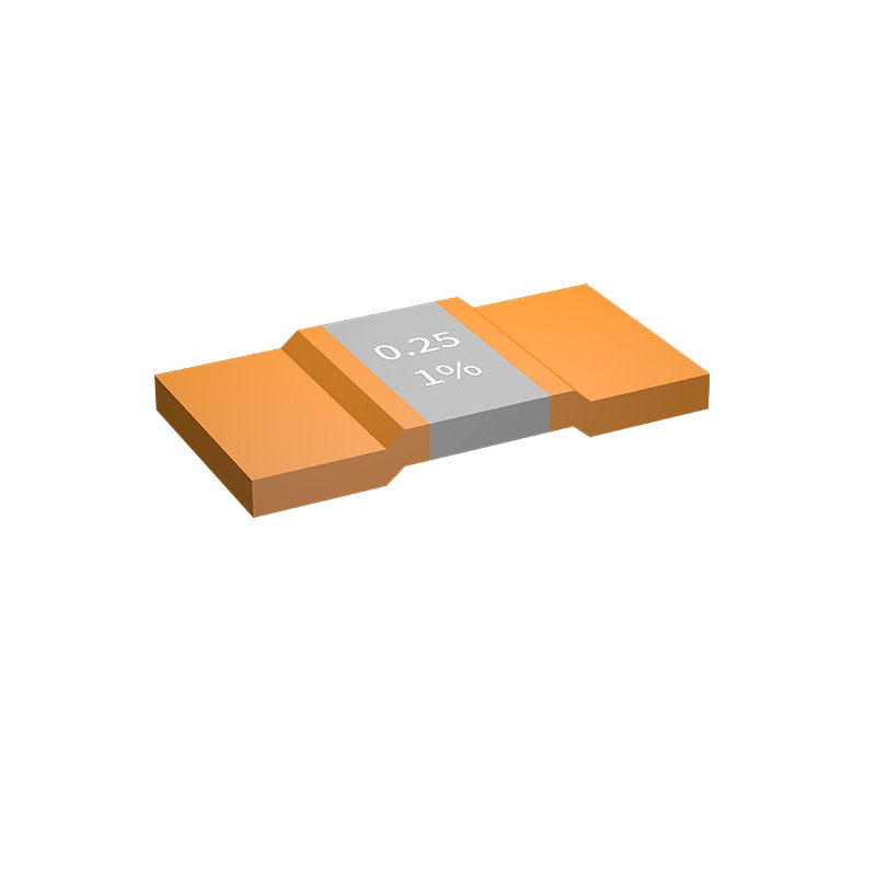
The distinction between thin film and thick film technologies goes far beyond their names, touching the core of what makes a circuit reliable. Thin film resistors are crafted through vapor deposition, etching precise patterns onto a ceramic base, resulting in layers measured in angstroms. Thick film, on the other hand, relies on screen-printing pastes and firing them, building up layers tens of microns thick. When a design can tolerate wider tolerances, thick film often wins on cost. But the moment accuracy, long-term stability, or temperature stability becomes non-negotiable, the conversation shifts dramatically.
Thin film’s precision stems from its fabrication process. Photolithography carves out exactly the right geometry, yielding initial tolerances as tight as ±0.01% and temperature coefficients of resistance near 5 ppm/°C. These numbers aren’t just datasheet decorations—they mean a sensor circuit stays locked onto its signal without drift over years. In medical instrumentation or aerospace guidance, where a fraction of a percent error could cascade into a costly failure, the choice for thin film is almost automatic. It’s not that thick film can’t serve in these areas, but its inherent granular structure and laser trimming limitations cap its stability and noise performance.
Yet thick film holds its ground in applications where real-world constraints like board space, power ratings, and sheer volume dictate priorities. It handles higher power densities and uneven substrates more gracefully, and its lower cost supports mass production without breaking budgets. The engineering decision, then, is less about one being universally better and more about which compromise you can afford. When precision demands a choice, it forces you to look past the glossy specs and examine where a component’s behavior actually touches your circuit’s performance.
Minimizing Noise in Sensitive Analog Front-Ends
Careful PCB layout forms the first line of defense against noise in analog front-ends. Keep high-impedance traces short and surround them with ground pour to shield against capacitive coupling. Separate analog and digital grounds, joining them at a single star point beneath the ADC or amplifier. Place bypass capacitors within millimeters of power pins, using a combination of low-ESR ceramics and larger tantalums to maintain low impedance across a wide frequency range. Every via and corner in the return path can inadvertently create loop area, so route critical signals over an unbroken ground plane and avoid slot antennas in the copper.
Beyond layout, component selection and circuit architecture play equally vital roles. Choose resistors with low excess noise—metal film types are usually preferable to thick-film in the signal path. Operate amplifiers in gains that keep their voltage noise dominant over current noise through source impedance, and when dealing with photodiodes or high-impedance sensors, bootstrapping techniques can effectively neutralize input capacitance and reduce current noise contribution. Differential signaling and fully balanced signal chains reject common-mode interference that single-ended designs cannot, and twisting or pairing gain-setting and feedback resistors cancels magnetic pickup.
Power supply cleanliness often makes or breaks a sensitive measurement. Linear regulators with high PSRR at the frequencies of interest should feed the analog stages, but even then, “quiet” 50/60 Hz hum and rectifier spikes can sneak through. Passive RC filtering on supply lines, augmented by ferrite beads that transition to resistive loss at high frequencies, can dampen remaining ripple. In extreme cases, battery power or isolated DC-DC converters with post-regulation eliminate ground-loop noise entirely. Finally, capture noise floor and SNR data early using a spectrum analyzer or the ADC’s own Fast Fourier Transform—correlating spikes with known sources like switching supplies or digital clocks—and iterate on shielding and routing until the front-end delivers the resolution your sensor deserves.
Keeping Cool: Power Derating for Long-Term Stability
Every electronic component generates heat when it operates. As temperatures rise, the materials inside expand and contract, accelerating wear and eventually leading to failure. Power derating is a deliberate practice where a device is operated well below its maximum rated power, reducing internal heat generation. This isn't just a safety margin—it's a fundamental strategy to preserve long-term stability. By intentionally running components at lower stress levels, engineers can dramatically extend operational lifetimes and avoid thermal runaway scenarios that compromise entire systems.
The relationship between temperature and reliability is well understood: for many semiconductors, each 10°C reduction in junction temperature can double the expected lifespan. Keeping components cool through derating shifts the failure mechanisms from sudden, high-energy events to gradual, manageable degradation. Even in designs with active cooling, passive margins built into the power budget ensure that local hot spots don't sneak past thermal limits. Over the years, field data consistently shows that systems operating at high derating factors experience fewer unexplained outages and maintain performance closer to original specifications.
Practically, achieving effective derating involves careful component selection, conservative thermal simulations, and sometimes simply allowing more board space for heat spreading. It’s not always about adding larger fans or heatsinks—sometimes the smartest move is to choose a component rated for twice the expected load, accepting a slight cost increase for a massive gain in ruggedness. This approach acknowledges that real-world environments are rarely as clean or steady as lab conditions; dust, altitude, and aging fans all chip away at cooling capacity. Building in a thermal cushion from the start is one of the most cost-effective ways to ensure that a product keeps running smoothly years after installation.
Parasitic Inductance and Capacitance: The Hidden Circuit Elements
Every real-world component carries subtle, unintended electrical properties that can quietly reshape circuit behavior. Parasitic inductance appears in leads, traces, and even internal wiring, adding a small but measurable opposition to changes in current. Similarly, parasitic capacitance forms wherever two conductors sit at different potentials, separated by an insulator—between PCB layers, adjacent traces, or inside the windings of a transformer. Though individually tiny, these stray elements accumulate, coupling unwanted signals, distorting waveforms, and triggering oscillations in circuits that might otherwise perform flawlessly.
At high frequencies, parasitics stop being mere imperfections and start dictating performance. A few nanohenries of lead inductance can ring with gate capacitance in a switching regulator, causing voltage overshoots that stress components. A picofarad of unintended coupling between an amplifier’s input and output can transform it into an oscillator. Even a simple wire becomes a transmission line, its impedance no longer negligible. Designers quickly learn that a schematic is an idealized sketch—the actual layout, with all its hidden RLC networks, is the real circuit.
Managing these invisible influences is part art, part engineering. Careful layout, such as shortening high‑current loops and using ground planes, can minimize parasitic inductance. Guard rings and shielding tame capacitive coupling. In some cases, parasitics are deliberately exploited—forming part of a filter or a resonant tank—turning a liability into an asset. Understanding that every trace, pad, and via contributes to a distributed, three‑dimensional network forces a shift in perspective: the physical world is always embedded in the design, whether we acknowledge it or not.
Beyond the Datasheet: Assessing Real-World Reliability
Spec sheets promise flawless performance under ideal lab conditions, but reliability in the field often tells a different story. Temperature swings, vibration, dust, and inconsistent power reveal weak points no datasheet can capture. That’s why seasoned engineers lean heavily on accelerated life testing and historical failure analysis from actual deployments. A component might survive 1,000 hours at rated temperature and humidity, yet still fail prematurely when slightly misaligned in a cramped enclosure where airflow is restricted. Bridging this gap means looking past marketing claims and actively tracking how real-world stress factors compound over time.
Derating guidelines offer a starting point, but they rarely account for cumulative damage from transient loads or the corrosive effect of airborne contaminants in industrial settings. Smart teams supplement manufacturer data with in-house reliability testing that mimics their specific operating profile—cycling power in rapid succession, introducing micro-vibrations, or exposing assemblies to salt fog. These custom protocols often uncover marginal designs that pass standard qualification tests but degrade unpredictably when pushed outside narrow boundaries. Sharing such field-gathered evidence within engineering communities has gradually become an unofficial, yet indispensable, reliability database that no formal standard can replicate.
Ultimately, confidence in a component stems from a blend of supplier transparency and brutal honesty about its limitations. When a vendor openly discusses failure modes instead of burying them in fine print, it signals a mature understanding of reliability as a dynamic, use-case-dependent trait. The transition from theory to practice requires constant feedback loops: every unexpected outage is a data point that refines future selection criteria. By treating every deployment as an ongoing experiment rather than a one-off design, organizations can build systems that are resilient not just on paper, but where it counts—out in the chaos of the real world.
FAQ
In precision circuits, the most critical parameters include tolerance, temperature coefficient of resistance (TCR), power rating, and stability under load. Also consider parasitic elements if the circuit operates at high frequencies, as well as long-term drift for sustained accuracy.
TCR indicates how much the resistance value changes with temperature. In precision applications, even small temperature variations can cause significant errors, so low TCR resistors (e.g., ±25 ppm/°C or less) are essential to maintain accuracy across a wide temperature range.
Tolerance specifies the allowable deviation from the nominal resistance. In high-accuracy circuits like voltage dividers or reference networks, tight tolerance (0.1% or better) ensures that the actual resistance is close to the design value, minimizing initial error.
Power rating determines how much heat a resistor can safely dissipate. Exceeding it leads to overheating, resistance drift, and eventual failure. In precision circuits, operating well below the rated power (often derated by 50% or more) reduces temperature rise and improves long-term stability.
Chip resistors have inherent parasitic inductance and capacitance due to their construction. At high frequencies, these parasitics can alter the impedance, causing signal distortion or resonance. Choosing resistors with low parasitic design (e.g., thin film with wraparound terminations) helps preserve signal integrity.
Thin film resistors offer tighter tolerances, lower TCR, lower noise, and better high-frequency behavior compared to thick film. They are typically chosen for precision analog circuits, instrumentation, and RF applications where accuracy and stability are paramount.
Four-terminal (Kelvin) current sense resistors separate current-carrying and voltage-sensing terminals, eliminating the voltage drop errors caused by lead or trace resistance. This is crucial when measuring high currents with high accuracy, as in power management and battery monitoring circuits.
VCR describes how resistance changes with applied voltage. In high-voltage precision circuits, a significant VCR can introduce nonlinearity and measurement errors. Selecting resistors with low VCR (usually thin film or specialized designs) ensures that resistance stays stable under varying voltage conditions.
Conclusion
Precision circuit design demands meticulous chip resistor selection, beginning with an understanding of tolerance and temperature coefficients. Tight tolerance resistors (e.g., 0.1% or better) paired with low TCR (like ±25 ppm/°C) ensure predictable performance over temperature shifts. The choice between thin film and thick film technology is pivotal: thin film offers superior stability, lower noise, and finer tolerances, making it ideal for high-accuracy applications, whereas thick film may suffice where cost and size are primary. In sensitive analog front-ends, resistor noise—especially excess noise in thick films—can degrade signal integrity, so choosing low-noise thin film resistors and optimizing resistance values becomes critical.
Beyond basic specifications, thermal management is essential; power derating according to the manufacturer's curves prevents drift and extends lifespan. Parasitic inductance and capacitance, inherent in resistor construction, can introduce resonances or filtering effects that compromise precision at high frequencies, requiring careful layout and sometimes non-standard footprints. Finally, reliability transcends datasheet promises—factors like moisture sensitivity, board flex, and long-term drift must be evaluated through accelerated testing or field data. A professional approach integrates all these facets, balancing performance, cost, and dependability for the intended precision circuit.
Contact Us
Contact Person: Yuying Gao
Email: [email protected]
Tel/WhatsApp: +86 18926013721
Website: https://en.milliohm.net/