
Substantial Oil-Immersed Transformer Guide for High Capacity Power Systems
2026-09-20
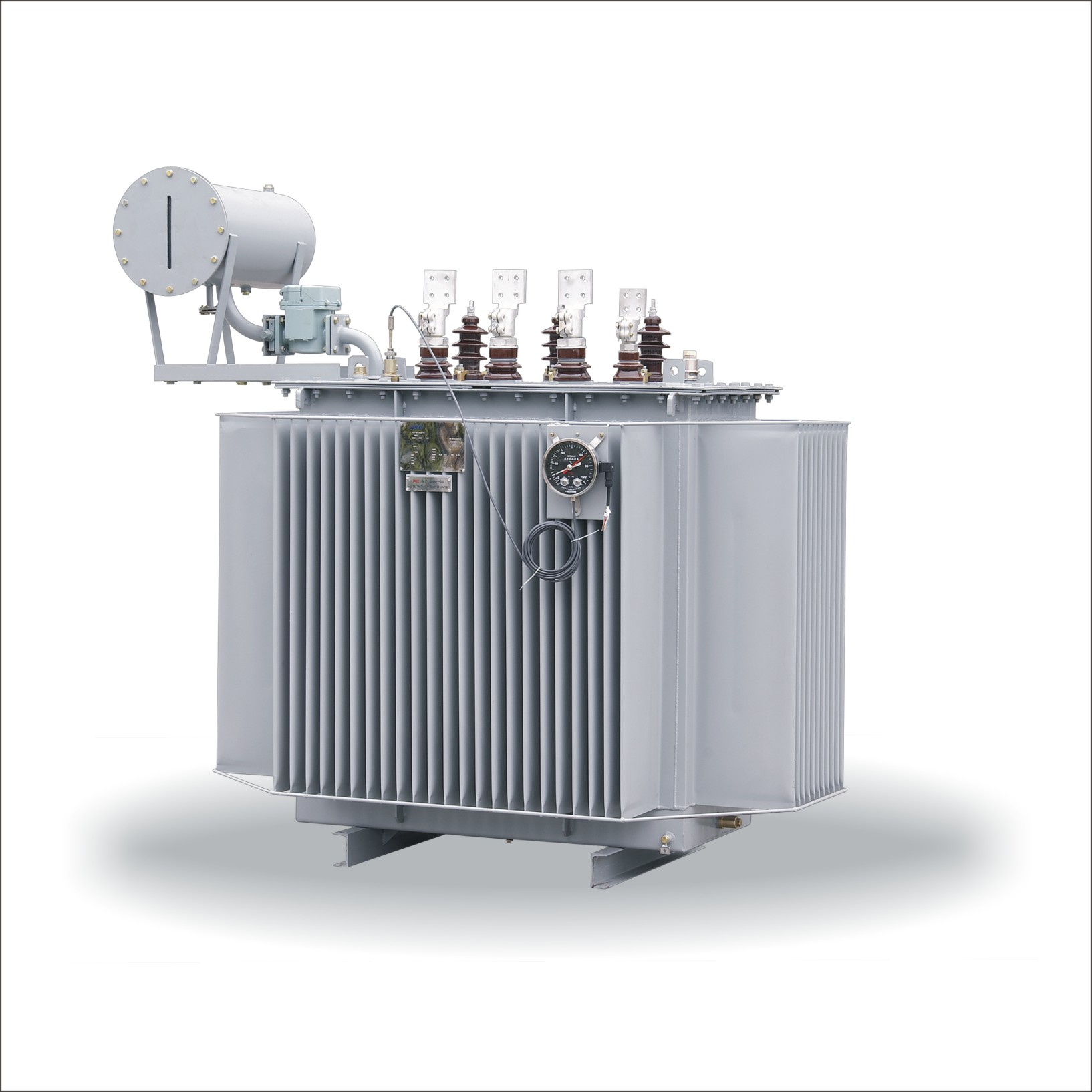
High-capacity power systems don’t forgive guesswork. When a transformer’s oil-immersed core is pushed to its thermal and dielectric limits, every design decision echoes through decades of service—or failure. This guide strips away the noise and focuses on what actually matters for substantial oil-immersed transformers: insulation integrity, cooling dynamics, load cycling, and the maintenance rituals that separate a resilient asset from a costly outage. Whether you're specifying a new unit or nursing an aging fleet, you'll find field-tested insights that go beyond datasheet promises. And if you're sourcing hardware built to these standards, Chang Song has been quietly engineering transformers for the demands most manuals won't mention.
Oil Duct Spacing and Hot-Spot Limits in Large Core-Form Units
Large core-form units push oil duct spacing into a delicate balancing act. The gap between adjacent winding sections does more than just create a path for oil; it sets the local flow resistance, determines how much oil reaches the hottest copper, and influences the mechanical stiffness of the winding stack. If the duct is too narrow, pressure drop rises sharply and the oil in that region can stagnate, leaving heat to accumulate even when average winding temperatures look fine. If it is too wide, the core and coil assembly grows unnecessarily, increasing copper length, stray losses, and tank size.
Hot-spot limits in this context rarely follow the simplest assumptions. A hotspot does not automatically sit at the very top of the winding; it often develops where oil velocity drops, where a horizontal barrier redirects flow, or where local eddy losses spike near the ends of the winding. Designers typically target a maximum conductor-insulation temperature well below the accelerated-aging threshold, but the margin can be eroded by an unnoticed choke point in a narrow duct. So the actual limiting criterion becomes a search for the worst combination of duct width, oil flow distribution, and loss intensity.
Practical fixes in large units often involve rearranging the oil circuit rather than simply widening every duct. By staggering washers, adjusting vertical spacer placement, and using directed-flow sections, engineers can force oil through previously starved channels and pull the hotspot down several degrees without a major size penalty. In some designs, a few strategically widened ducts near the top of the winding do more for hotspot control than uniform extra clearance throughout the stack. This is why modern core-form designs treat oil duct spacing as a local tuning parameter, not a global one-size-fits-all dimension.
Dissolved Gas Analysis Under Rapid Load Profile Swings
When the load on a transformer changes quickly, the thermal conditions inside the tank are no longer stable. Dissolved gas analysis, which is normally built around the assumption of a slowly drifting temperature profile, can yield readings that look alarming but are simply the result of gas migration lag. Hydrogen and methane diffuse into the oil much faster than heavier gases like ethane and ethylene, so a sample taken during or immediately after a rapid swing may show ratios that do not reflect the actual fault condition.
Another complication is that rapid load changes often create short-lived hot spots near windings or connections. These spots generate gases only for a few minutes at a time, and the gas bubbles may take hours to distribute evenly through the oil. If a sample is drawn before mixing is complete, local concentrations can be misleading. A high reading in one sample followed by a much lower reading in the next does not always mean the fault has disappeared; it may simply mean the gas has not yet equilibrated.
To interpret DGA data under such conditions, it helps to compare samples taken at similar points in the load cycle and to track trends over multiple cycles rather than relying on a single snapshot. Paying attention to the load profile at the moment of sampling can prevent unnecessary shutdowns and help distinguish between transient thermal stress and genuine insulation degradation.
Cellulose Moisture Drift After Factory Drying
Factory drying sets a baseline moisture content for cellulose, but that number rarely survives contact with real storage and shipping conditions. The material leaves the line at a tightly controlled percentage, then immediately begins interacting with ambient humidity through pallet wrapping, container walls, and even the air trapped between fibers. This drift is not a flaw so much as a physical inevitability: cellulose is hygroscopic, and its moisture level will keep shifting until it reaches equilibrium with the surrounding environment.
The rate and direction of drift depend heavily on how the dried cellulose is packed and where it sits afterward. A sealed vapor-barrier bag in a cool warehouse may hold the factory moisture reading for weeks, while open bales in a humid loading dock can pick up a full percentage point within days. Temperature swings make it worse, because warm air carries more water and can drive moisture deeper into the stack before condensing near the outer layers.
For anyone relying on that factory number for downstream processing or installation, the practical answer is to measure again at point of use. Expecting the dried value to remain static ignores how cellulose behaves outside the controlled line. Simple spot checks with a calibrated moisture meter, especially after long transit or seasonal shifts, give a truer picture than any certificate printed at the plant.
Tap Changer Contact Wear Under High-Cycle Switching
Repeated high-cycle switching imposes a cumulative mechanical and electrical burden on tap changer contacts that often goes unnoticed until performance shifts. Each operation triggers a brief arc as current transfers from one tap to the next, and with thousands of cycles per year, surface erosion becomes measurable. Hardened copper alloys, even those with silver plating, gradually lose contact area, while spring tension relaxes and alignment drifts. The result is not immediate failure but a slow rise in contact resistance, which compounds thermal stress and accelerates further wear.
Field inspections after extended high-cycle duty frequently reveal pitting, material transfer, and oxide film buildup that differ markedly from lab-aged samples. This is because real switching combines mechanical impact, slight misalignment, and variable load currents in ways static tests cannot fully replicate. Contacts that operate near rated current tend to show broad, shallow erosion, whereas lighter loads often produce localized transfer spikes due to longer arc duration per switch. Understanding these patterns helps maintenance teams distinguish normal aging from early signs of abnormal wear.
Mitigating contact wear under high-cycle conditions starts with tightening control parameters: reducing unnecessary tap changes, verifying synchronization between diverter and selector switches, and monitoring contact temperature trends. Some utilities now use ultrasonic or vibration signatures to detect subtle changes in contact mating before resistance drift becomes critical. Slightly increasing contact overtravel during refurbishment also compensates for material loss, though overdoing it can accelerate mechanical fatigue. Ultimately, extending contact life means treating wear as a dynamic system response rather than a fixed lifetime number.
Short-Circuit Force Distribution Across Clamping Structures
During a short-circuit event, the electromagnetic forces generated within transformer windings do not act as a single lumped load. Instead, they travel outward through the insulation, press rings, and coil support blocks before reaching the main clamping frame. The distribution across these structures is rarely uniform: local winding geometry, asymmetry in lead arrangement, and variations in preload from clamping bolts all shift the force peaks toward certain regions. In many core-form designs, the radial force component tends to concentrate near the outer edges of the winding, while the axial component splits unevenly between upper and lower clamping assemblies depending on winding height and any residual gap between the winding and the yoke.
The mechanical path also matters more than the peak magnitude at the winding surface. Once the force enters the clamping system, it divides among tie rods, finger plates, and the steel core frame according to local stiffness rather than simple cross-sectional area. A stiff core limb will attract a larger share of the radial load, leaving adjacent clamp arms to carry less than a naive load-sharing calculation would suggest. Bolted connections introduce additional nonlinearity: if the preload is insufficient, small separations open and close during the fault, causing abrupt shifts in the load path and localized stress spikes at bolt holes or fillet welds.
Field failures often trace back to these uneven distributions. A clamping structure that looks robust under static test conditions can develop cracks near welded stiffeners or loose tie rods after repeated fault duty, not because the total force exceeded the design limit, but because one member repeatedly absorbed more than its intended share. For that reason, modern assessments rely less on total short-circuit force and more on measured strain distribution across the actual clamping assembly, including the effects of manufacturing tolerances and aging of insulation materials.
Oil Reclamation Without Losing Oxidation Stability
The idea that reclamation necessarily sacrifices oxidation stability comes from older, aggressive methods. Harsh acid/clay treatments or high-temperature stripping often remove the very molecules that protect the base oil from oxygen attack. Yet a growing number of reclaimers now avoid this trade-off by focusing on contaminant removal rather than broad chemical alteration.
Modern systems can combine vacuum dehydration, fine filtration, and selective adsorption under a nitrogen blanket. This keeps dissolved oxygen low during processing, while carefully chosen adsorbents pull out polar degradation products, sludge precursors, and moisture without capturing the phenolic or aminic antioxidants still active in the fluid. Any antioxidant depletion is then corrected with a small, calculated dose of fresh inhibitor blend matched to the oil's original formulation.
The result is a reclaimed oil that retains or even improves its oxidation life. Routine testing with rotating pressure vessel oxidation test (RPVOT) or the turbine oil stability test (TOST) often shows minimal loss compared to virgin oil, and sometimes a slight gain when the add-back package is optimized. This shifts reclamation from a last-resort disposal alternative to a practical life-extension strategy.
FAQ
Focus on load profile growth, short-circuit withstand capability, cooling class, impedance, and insulation coordination. Site altitude, ambient temperature, and seismic requirements also shape the design more than many expect.
It reveals incipient thermal or electrical faults by measuring gases like hydrogen, methane, ethylene, and acetylene in the oil. Trending gas ratios over time can identify overheating, partial discharge, or arcing long before a trip occurs.
ONAN, ONAF, and OFAF or OFWF are common. Natural cooling suits moderate loads, while forced oil and forced water systems raise capacity but add auxiliary power, pump maintenance, and failure modes.
Moisture sharply accelerates cellulose aging and lowers dielectric strength. Even a 0.5% increase in paper moisture can cut insulation life by half, so dry-out procedures and sealed conservator systems matter more than oil test results alone.
Watch for rising oil temperature near the diverter compartment, unexplained gas formation especially acetylene, erratic voltage ratios during operation, and increased contact wear seen during inspections.
Every six to twelve months is a solid baseline for critical units. If alarms appear or the transformer runs under sustained overload, shorten the interval to catch trend shifts before they become failures.
It keeps ambient air and moisture away from the insulating oil while allowing oil volume to change with temperature. This slows oxidation and water ingress, extending both oil and paper life.
Consider it when fire safety, environmental compliance, or overload capability improvements outweigh the cost. Natural esters have higher fire points and slow paper aging, but require compatibility checks for gaskets, paints, and cooling design.
Conclusion
Large core-form oil-immersed transformers demand careful attention to oil duct spacing and hotspot control. In high-capacity units, narrowing ducts to boost dielectric strength can backfire if oil flow becomes restricted, pushing winding temperatures past accepted limits. Field experience shows hotspots often cluster near upper disc sections where directed oil flow is weakest. Dissolved gas analysis remains the most reliable early warning under rapid load swings, but interpreting DGA trends requires understanding the thermal and electrical stress history; a sudden acetylene rise after cyclic peaking is not always an active fault, sometimes it reflects accumulated gas release from stagnant oil pockets. Cellulose moisture drift after factory drying adds another layer. Even well-sealed units absorb moisture through gaskets and bushings during transport and storage, shifting the moisture equilibrium toward the paper and reducing dielectric margin.
Tap changer contact wear under high-cycle switching deserves equal scrutiny. Frequent voltage regulation in renewable-heavy grids accelerates contact erosion and coking; oil filtration alone cannot restore surfaces once pitting starts. Short-circuit force distribution across clamping structures reveals uneven axial and radial loading, particularly in aged transformers where insulation shrinkage loosens the winding stack. Re-tightening alone may shift stress to weaker end insulation. Finally, oil reclamation without losing oxidation stability calls for selective adsorbent treatment or low-temperature degasification rather than aggressive clay polishing, which strips natural inhibitors. In practice, a condition-based approach—combining oil tests, thermal imaging, and switching counters—keeps these large units reliable well beyond nameplate expectations.
Contact Us
Contact Person: Tonglun Chen
Email: [email protected]
Tel/WhatsApp: 8618906642555
Website: https://www.cncsele.com