
Top Current Sensing Resistor Options for Precise Current Measurement
2026-08-31
Few components influence measurement accuracy as quietly as the current sensing resistor. Pick the wrong one and you’ll see unstable readings, thermal drift, or blown tolerance budgets; pick the right one and your design just works. This article walks through the top current sensing resistor options for precise current measurement—comparing low-ohm metal strip, wirewound, and metal foil types where it matters. For a practical side-by-side look at what actually survives real circuit conditions, Milliohm has done the heavy lifting.
Metal Foil Resistors for Uncompromising Precision
A metal foil resistor starts with a cold-rolled nichrome foil several micrometers thick, bonded to a ceramic substrate. Unlike thin-film or thick-film deposition, this bulk foil is then patterned with photolithography and laser-trimmed, which preserves the alloy's crystalline structure. The result is a resistive element almost free of the internal stresses that cause drift in other technologies.
The numbers speak plainly. Resistance tolerances down to ±0.005% and temperature coefficients as low as ±0.2 ppm/°C are not laboratory exceptions but catalog values. Thermal EMF remains below 0.1 µV/°C at the leads, and load-life stability often stays within ±0.01% after 10,000 hours. Even under pulsed power or wide temperature swings, the foil element keeps its nominal value without the noise or hysteresis common in deposited films.
Such uncompromising precision finds its place in metrology bridges, precision current-sensing for battery test systems, and feedback networks in high-resolution data acquisition. Aerospace and medical instrumentation also rely on these parts because a single resistor can replace matched sets, reducing board space while improving repeatability across production batches.
Wirewound Designs for Thermal Stability Under Load
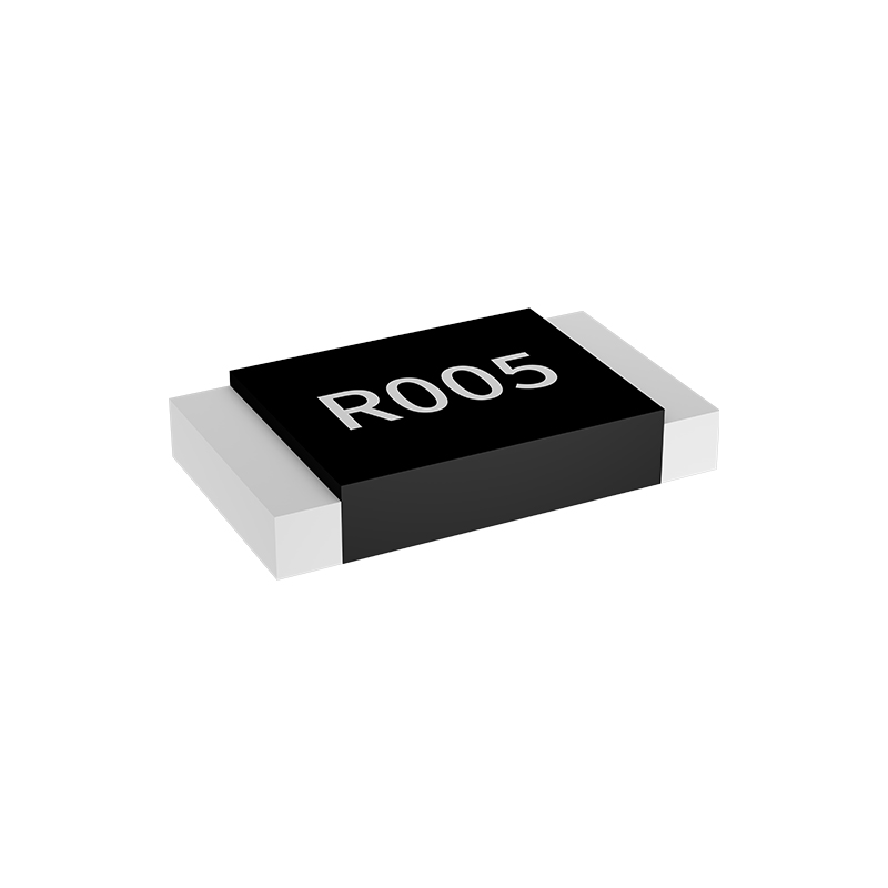
Wirewound resistors manage thermal stress through a combination of alloy selection and core geometry. Nickel-chromium and copper-nickel alloys are common because their resistivity shifts only slightly across a wide temperature band, which keeps the resistance value reliable even after repeated heating cycles. The wire is wound with controlled tension onto a ceramic or fiberglass core, leaving tiny gaps between turns that allow heat to escape without creating hotspots. This spacing also reduces the mechanical strain that builds up when the wire expands and contracts under load.
A vitreous enamel or silicone coating adds another layer of protection by sealing the winding against moisture and oxidation, both of which accelerate drift. Some designs use a non-inductive winding pattern—folding the wire back on itself—so that the resistor stays stable in high-frequency circuits where inductance would otherwise introduce errors. The end caps and lead attachments are also welded rather than soldered, because solder joints soften at elevated temperatures and become a common failure point. Together these choices let a wirewound part hold its tolerance even when it runs at 70–80% of its rated power for hours at a time.
Thick Film Current Sense Resistors in Space-Constrained Boards
Fitting precise current measurement into a board that already feels packed often comes down to the resistor you choose. Thick film current sense resistors earn their place here not through exotic materials, but through a practical balance of size, cost, and repeatable performance. Their low profiles—commonly 0.5 mm or less—let them slip under heatsinks or between tall capacitors without forcing a layout change, while standard footprints like 0402 or 0603 keep rework straightforward. The real advantage in tight spaces is thermal behavior: a well-specified thick film part spreads heat across its alumina substrate instead of concentrating it at the terminations, so you can push closer to rated power without cooking neighboring components.
Designers often overlook how much layout freedom comes from choosing the right resistance value early. With thick film current sense resistors, moving from 10 mΩ to 20 mΩ can halve the sense voltage drop but doubles the footprint’s thermal load—a trade-off that matters more when every square millimeter is contested. Many boards end up with parallel resistor arrays simply because a single larger part would break the ground plane or block a via field. A compact thick film option sidesteps that by offering lower resistance in the same package, letting you keep the sense loop tight and the measurement clean without bending the layout rules.
One underappreciated detail in dense designs is the resistor’s height relative to surrounding passives. A current sense resistor that stands 0.2 mm taller than the adjacent MLCCs can become the unintended high point for wave soldering or conformal coating, creating shadowing or uneven coverage. Thick film parts with a flat, uniform top surface and consistent terminal plating avoid this; they seat flush against the board and leave no raised edges to snag during pick-and-place. When every component is competing for the same z-height budget, that kind of predictability is worth more than a marginal improvement in TCR or tolerance.
Four-Terminal Kelvin Resistors for Milliohm-Level Accuracy
When measuring resistances below an ohm, the two-wire approach falls apart because the test leads and contact junctions introduce more error than the resistor itself. A four-terminal Kelvin connection splits the current path from the voltage sense path. The outer pair forces a known current through the device, while the inner pair samples the voltage drop directly across the resistive element. Because the sense terminals draw almost no current, their lead resistance and contact resistance drop out of the measurement, leaving only the true milliohm value.
In practice, Kelvin resistors for milliohm accuracy are built with dedicated sense taps rather than simple wire extensions. The geometry matters—voltage taps are placed precisely at the current path boundaries so that the sensed region matches the defined resistance. This reduces errors from current spreading and uneven current density. Materials also play a role: low-thermal-EMF alloys for the terminations prevent junction voltages from swamping the tiny signal, and a low temperature coefficient of resistance keeps the value stable as the part self-heats under load.
Achieving repeatable milliohm-level results still demands careful board layout and measurement technique. Sense traces should run as differential pairs, kept away from high-current loops, and the current source should be stable enough that its noise does not appear in the voltage reading. Thermal gradients across the resistor can generate microvolt-level offsets, so symmetrical copper and thermal relief are part of the design. When these details are handled, a four-terminal Kelvin resistor becomes a dependable reference for current sensing, battery impedance checks, or low-value shunt calibration.
Bulk Metal Alloy Shunts for Low Thermal EMF
In precision current measurement, spurious thermal EMFs arising from temperature gradients across conductor junctions can easily swamp microvolt-level signals. Bulk metal alloy shunts tackle this by using alloys with intrinsically low Seebeck coefficients relative to copper, such as manganin or zeranin. A solid machined block also spreads heat more evenly than a thin foil, so the temperature difference between the two voltage-sensing points stays below a few millikelvin in practice.
Manganin remains the workhorse for low thermal EMF shunts because its thermoelectric potential against copper is typically under 1 µV/°C, and its resistance drift with ambient temperature is minimal. Constantan, despite its excellent resistivity stability, develops a much larger thermal voltage against copper and should be avoided where polarity reverses or where the shunt may sit in a moving air stream. For higher temperature operation, nickel-chromium-aluminium alloys like Evanohm offer a useful compromise, though they need careful heat sinking to keep the temperature gradients symmetric.
Practical construction matters just as much as alloy choice. The voltage sense terminals must be placed on an isothermal plane, ideally on the narrow neck of the shunt element. Bolted copper lugs can create unwanted thermocouple junctions unless the surfaces are clean, flat, and torqued consistently. A common trick is to mount the shunt inside a small thermal enclosure or wrap it with copper braid so that both ends see the same ambient temperature, reducing the net thermal EMF to a few nanovolts in well-designed metrology setups.
High-Power Shunt Resistors for Continuous Current Monitoring
High-power shunt resistors serve as the front-line sensing elements when currents climb beyond what hall-effect or transformer-based probes can handle reliably. In continuous monitoring setups, these components are typically built from manganin, nichrome, or electron-beam welded copper-nickel alloys, with resistance values from 0.05 mΩ up to a few milliohms. Their low resistance keeps the voltage burden small even at hundreds of amps, but that advantage hinges on keeping the sensing path's parasitic inductance and contact resistance well below the shunt's own tolerance.
Heat management sets the practical ceiling for continuous use. A 0.1 mΩ shunt carrying 400 A dissipates 16 W, which may sound modest, but without a direct thermal path to a busbar or heatsink, the resistive element can easily drift past its specified temperature coefficient. High-power versions rely on solid copper terminals, sometimes integrated into the busbar stack itself, and are often derated according to ambient temperature, airflow, and the available PCB copper area if surface-mounted. Four-terminal Kelvin connections become non-negotiable here, since even a few milliohms of lead resistance can swamp the measurement.
In practice, these shunts show up in battery management racks, electric vehicle inverters, and industrial motor drives where the load runs for hours or days without interruption. Selecting one involves more than a wattage figure: the temperature coefficient of resistance, thermal EMF against copper, and long-term stability under thermal cycling all shape how trustworthy the current readings remain. Some designs add laser-trimmed calibration notches or notched geometry to fine-tune resistance without introducing hot spots, giving maintenance teams a clear, drift-free signal year after year.
FAQ
Metal alloy, thick film, thin film, and wirewound resistors dominate the market. Metal alloy parts usually offer the lowest resistance values and best surge tolerance, while thin film provides excellent TCR and long-term stability. Thick film is cost-effective for less demanding applications, and wirewound works well when you need high power dissipation though it introduces more inductance.
Start with your maximum current and the maximum acceptable voltage drop. Lower resistance minimizes power loss and self-heating, but it also reduces the voltage signal you're trying to measure, which can hurt resolution. Many designs settle between 1 mΩ and 100 mΩ for high-current paths, while low-current precision circuits may go higher.
As the resistor heats up from the current passing through it, its resistance shifts. A high TCR means that shift is large enough to introduce measurement error, especially across a wide ambient temperature range. For precision work, look for resistors with a TCR below 50 ppm/°C, and consider self-heating effects at full load.
If you're measuring very small voltages across a low-value shunt, the resistance of the solder joints and PCB traces can easily overwhelm the resistor's own value. A four-terminal Kelvin connection separates the current path from the voltage sense path, so your measurement only sees the resistor itself, not the lead and contact resistance.
Metal alloy resistors achieve very low resistance without sacrificing too much on tolerance or surge handling. They also tend to have lower thermal EMF and better pulse performance. Thick film resistors are cheaper but their resistance can drift more under high stress, and they often need larger footprints to handle the same power.
In switching converters or motor drives, fast current changes across an inductive shunt create voltage spikes that corrupt the current measurement. Look for resistors with low inductance, often achieved through serpentine or folded element designs, or use coaxial and Kelvin layouts to reduce loop area.
Running the sense traces from the middle of the pad rather than at the exact resistor termination point can add significant copper resistance. Also, placing the resistor too close to heat sources or not providing enough copper for heat spreading can cause thermal gradients that change the resistance. Keep Kelvin sense traces short, differential, and away from noisy switching nodes.
Yes, especially if you're measuring DC or low-frequency currents at low voltage levels. Dissimilar metal junctions between the resistor, solder, and copper traces can generate small thermoelectric voltages that look like a current signal. Choose resistors with low thermal EMF specifications and try to keep both sense connections at the same temperature.
Conclusion
Precise current measurement starts with selecting a resistor whose construction matches the circuit's tolerance, thermal, and space demands. Metal foil resistors deliver uncompromising precision by minimizing temperature coefficient and long-term drift, making them the default when a few milliohms of change can skew control loops. Wirewound designs earn their place under sustained load, since their bulk-wound elements absorb power without dramatic resistance shifts, preserving measurement linearity. On densely packed boards, thick film current sense resistors offer a practical compromise: compact footprints and low cost, though their noisier profile limits use to less critical rails. For milliohm-level accuracy, four-terminal Kelvin resistors separate the current path from the voltage sense path, removing lead and pad resistance errors that would otherwise swamp small signals.
Beyond geometry, material chemistry drives low-level performance. Bulk metal alloy shunts are prized for low thermal EMF, a factor often overlooked until thermocouple effects between resistive element and copper traces inject microvolt noise into the sense line. High-power shunt resistors extend this reliability into continuous current monitoring, where heat must be dissipated without derating accuracy or causing solder joint fatigue. The real differentiator is matching resistor behavior to the signal level and environment: a Kelvin foil part suits a precision battery gauge, while a thick film chip may handle a motor phase with enough margin. By weighing drift, board area, power handling, and parasitic voltage sources together, designers can choose a sensing resistor that remains stable over time instead of fighting calibration drift month after month.
Contact Us
Contact Person: Yuying Gao
Email: [email protected]
Tel/WhatsApp: +86 18926013721
Website: https://en.milliohm.net/